1.3 Cut-Free and Free Body Diagram
Imagine we are the Sherlock Holmes of the engineering world. Instead of solving crimes, we solve puzzles of statics and dynamics. Our superpower? Cutting free and creating free body diagrams.
It's simple: We take a system (e.g., a beam, a bridge, a car, a hanging lamp, ...) and mentally cut it away from its surroundings. This allows us to isolate it and see all the forces acting on the system, as if there was nothing else in the world.
With cutting free, we can:
-
Track down loads like detectives:
What forces are lurking in the shadows? Weight, wind pressure, friction - we expose them all!
-
Understand force ratios:
Which force is the greatest? Which forces act together? With the free body diagram, we have the inside scoop!
-
Keep systems in balance:
How do we have to design the system so that it remains stable and does not tip over or collapse? Cutting free shows us the way!
-
Find weak points:
Are there points in the structure that are particularly heavily loaded?
-
Optimize and improve:
How can we make the design more efficient and save material?
- Define the system: What part of the world do we want to investigate?
- Choose a cut line: Where do we cut the system off?
- Draw in the forces: What forces act on the cut-free system?
- Create a free body diagram: Draw the system with all its forces as a clear diagram.
With free body diagrams, we make invisible forces visible. They are like X-rays that show us the internal structure of a system and the loads acting on it. A free body diagram shows us not only the forces, but also their direction of attack and magnitude. It is therefore the representation of the cut-free object with all the forces acting on it.
Cutting free and free body diagrams are indispensable tools for engineers in all fields:
- Statics: Calculation of load-bearing structures such as bridges, buildings and towers
- Dynamics: Investigation of moving systems such as cars, airplanes and robots
- Mechanical engineering: Development of machines and engines
- Biomechanics: Analysis of body movements and loads
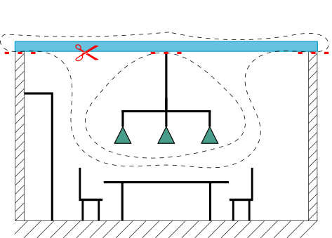
Let's imagine a beam that lies on two walls of a room. A heavy object, a lamp, hangs from it. We neglect the weight of the beam at this point.
We see the beam and the lamp. In addition, a table, two chairs and a cupboard. What we cannot see: What happens inside the beam? What forces are acting on it?

First, let's define our system. We want to investigate the beam, so it is our main system. The lamp is still attached to it, we consider it as a subsystem:

Now we cut free at the system boundaries:
Now we draw in the forces that act on our cut-free system:

In the last step, we create our free body diagram:

We have mentally cut the beam off from the ceiling. Now we see the weight of the lamp, the tensile force in the beam and the support forces of the walls.
Aha! By cutting free, we see that the tensile force in the beam must be equal to the weight of the lamp. This is the only way the cut-free lamp can remain in balance.
Furthermore, we see: The sum of the two support forces (FA and FB) must be equal to the force F and thus the weight G of the lamp - otherwise the cut-free beam would not be in equilibrium!
Whether bridge builder, aircraft developer or mechanical engineer - cutting free and free body diagrams are indispensable tools for all engineers. With these superpowers, we solve tricky puzzles and ensure that our world is stable and safe.
With these superpowers, we can:
- Understand and calculate forces in systems
- Find weak points in structures
- Design stable and safe systems
So, grab your mental scalpel and start cutting! The world of engineering mechanics is waiting to be explored by you!