Skip to main content Skip to page footer

Strength of Materials Exercise Collection

Are you ready to put your brain to the test in the exciting world of Strength of Materials? This section contains all the exercises you need to put your knowledge of stress state and moment of inertia to the test.

Here's how it works:

  1. Choose your topic: Sorted by learning content, you will find the tasks that have been published so far.
  2. Test your knowledge: Work through the tasks and check independently whether you have mastered the material.
  3. Solution paths: Do you need a helping hand? Detailed solution paths are available for all tasks upon request.

Why you should use this exercise collection:

  • Perfect for practice: Ideal for deepening your knowledge and preparing for exams.
  • With solutions: This allows you to correct your mistakes independently and close knowledge gaps.
  • Always up-to-date: We regularly add new tasks so that you are always up to date.

So what are you waiting for? Get started on the tasks and show what you're made of in Strength of Materials!

P.S.: Do you have any questions or feedback? Just send us an email.

Good luck!

Your team from TechMechAcademy

Concept of Online education. man use Online education training and e-learning webinar on internet for personal development and professional qualifications. Digital courses to develop new skills.

State of Stress

Uniaxial Stress State
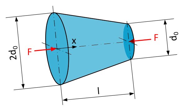
Practice Exercise F-1.1.1
The illustration depicts a round, tapering rod with a compressive force F along its axis of symmetry, represented by two red arrows pointing towards the circular surfaces at the beginning and end of the rod.
Conical Rod and Compressive Force

A conical rod with a circular cross-section and length \(l=250~\mathrm{mm}\) is loaded, as shown in Figure 1, by a compressive force \(F=10~\mathrm{kN}\) along the axis of the rod. The diameter at \(x=0\) is twice as large as the diameter at \(x=l\) with \(2d_0=150~\mathrm{mm}\) and \(d_0=75~\mathrm{mm}\), respectively.

  1. What is the formula for calculating the normal stress \(\sigma\) at any location x in a section perpendicular to the axis of the rod?
  2. What is the magnitude of the normal stress \(\sigma\) at the location \(x=200~\mathrm{mm}\) in a section perpendicular to the axis of the rod?
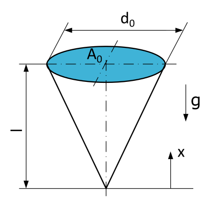
Practice Exercise F-1.1.2
The illustration depicts a circular cone with its base at the top and its apex at the bottom. The running coordinate x extends from the apex of the cone upwards. The gravitational acceleration g is indicated with an arrow pointing downward.
Suspended Cone

An icicle is hanging from a gutter. The icicle has the shape of a circular cone with a length \(l=10~\mathrm{cm}\), a diameter \(d_0=5~\mathrm{cm}\) at the suspension point, and a cross-sectional area \(A_0\). The ice has a density of \(\varrho = 0,91~\mathrm{g/cm^3}\).

  1. What is the formula for calculating the normal force \(N\) at any location x in a section perpendicular to the axis of the cone?
  2. What is the formula for calculating the normal stress \(\sigma\) at any location x in a section perpendicular to the axis of the cone?
  3. What is the magnitude of the normal stress \(\sigma\) at the location \(x=70~\mathrm{mm}\) in a section perpendicular to the axis of the cone?
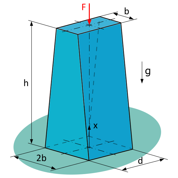
Practice Exercise F-1.1.3
The rod stands on an indicated ground. Its lower base is 2b x d, its upper base is b x d. Its height is dimensioned as h. From the top, it is subjected to a force F, represented by a downward arrow, along its axis of symmetry. The running coordinate x extends from the bottom to the top. The gravitational acceleration g is indicated with an arrow pointing downward.
A Loaded Homogeneous Bar with Constant Thickness and Linearly Variable Width

A homogeneous bar with constant thickness \(d=20~\mathrm{mm}\) and linearly varying width is subjected to a compressive force \(F=1~\mathrm{kN}\).

Given: \(b=15~\mathrm{mm}\), \(h=80~\mathrm{mm}\), \(\varrho = 7,85~\mathrm{g/cm^3}\)

  1. What is the formula for calculating the cross-sectional area \(A(x)\) at any location x in a section perpendicular to the axis of the rod?
  2. What is the formula for calculating the normal force \(N(x)\) at any location x in a section perpendicular to the axis of the rod?
  3. What is the magnitude of the normal stress \(\sigma\) at the location \(x=30~\mathrm{mm}\) in a section perpendicular to the axis of the rod?
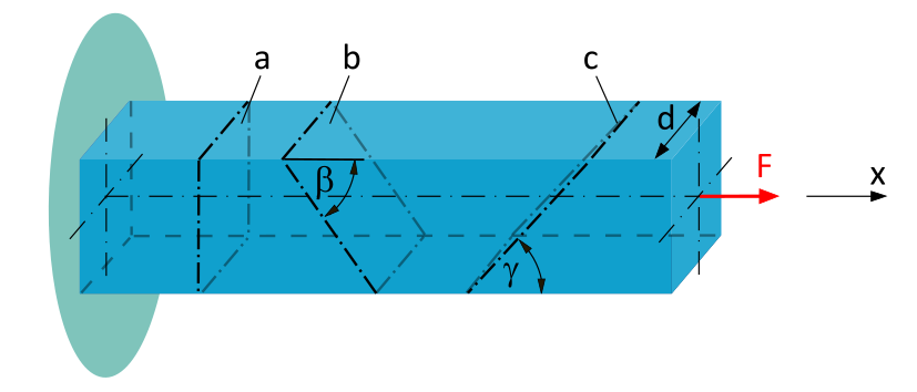
Practice Exercise F-1.1.4
The illustration shows a beam with a square cross-section, fixed on the left side. In the drawing, three sectional planes a, b, and c are indicated. Sectional plane a is perpendicular to the beam axis. Sectional plane b runs from the upper left to the lower right, with the given angle Beta describing the smaller angle at the top. Sectional plane c runs from the lower left to the upper right, with the given angle Gamma describing the smaller angle at the bottom. The side length of the cross-section is denoted as d. A tensile force F acts at the right end of the beam at the center of the cross-section.
Normal and Shear Stress at an Arbitrary Section Angle

A clamped beam with a square cross-section (side length \(d=20~\mathrm{mm}\)) is subjected to a tensile force \(F=10~\mathrm{kN}\) along the beam axis.

Determine the average normal stress and the average shear stress...

  1. ...acting in cross-sectional plane a.
  2. ...acting in cross-sectional plane b (\(\beta = 50°\)).
  3. ...acting in cross-sectional plane c (\(\gamma = 40°\)).

Plane Stress State
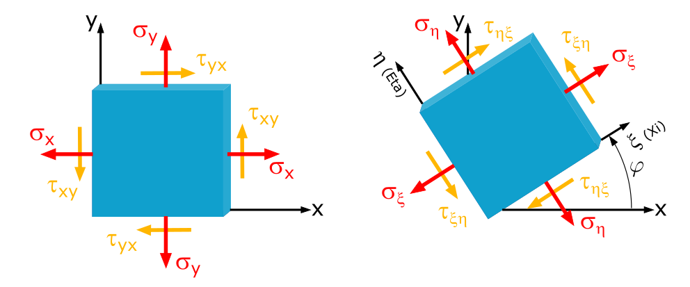
Practice Exercise F-1.2.1-xy
This illustration depicts a square sheet of metal in two positions. In one instance, it lies with two sides in an x, y-coordinate system with the origin at the bottom-left corner of the sheet. In the second position, it is tilted at an angle phi to the x-axis. The x-axis is positive to the right, and the y-axis is positive upward. Normal and shear stresses are represented for each side of the sheet, with arrows indicating their respective directions.
Plane Stress Transformation, x,y-Coordinates

In a sheet, the stresses \(\sigma_x = -250\mathrm{~MPa}\), \(\sigma_y = 80\mathrm{~MPa}\) and \(\tau_{xy} = 50\mathrm{~MPa}\) are given.

What normal and shear stresses occur at a section angle of \(\varphi=30°\)?
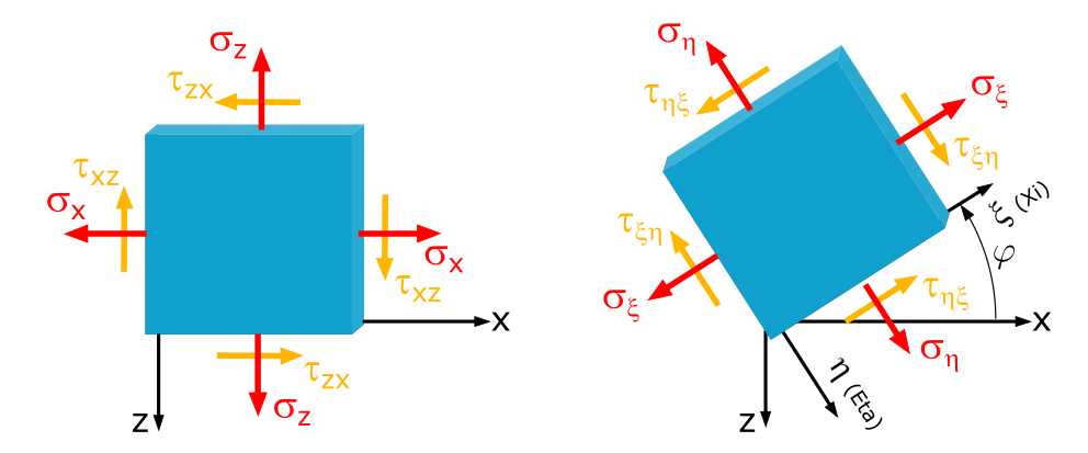
Practice Exercise F-1.2.1-xz
This illustration depicts a square sheet of metal in two positions. In one instance, it lies with two sides in an x, z-coordinate system with the origin at the bottom-left corner of the sheet. In the second position, it is tilted at an angle phi to the x-axis. The x-axis is positive to the right, and the z-axis is positive downward. Normal and shear stresses are represented for each side of the sheet, with arrows indicating their respective directions.
Plane Stress Transformation, x,z-Coordinates

In a sheet, the stresses \(\sigma_x = -250\mathrm{~MPa}\), \(\sigma_z = 80\mathrm{~MPa}\) and \(\tau_{xz} = 50\mathrm{~MPa}\) are given.

What normal and shear stresses occur at a section angle of \(\varphi=30°\)?
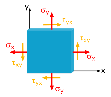
Practice Exercise F-1.2.2-xy
This illustration depicts a square sheet of metal. It lies with two sides in an x, y-coordinate system with the origin at the bottom-left corner of the sheet. The x-axis is positive to the right, and the y-axis is positive upward. Normal and shear stresses are represented for each side of the sheet, with arrows indicating their respective directions.
Determine the Magnitude and Direction of the Principal Stresses in the x-y Coordinate System

In a sheet, the stresses \(\sigma_x = 20\mathrm{~MPa}\), \(\sigma_y = 30\mathrm{~MPa}\) and \(\tau_{xy} = 10\mathrm{~MPa}\) are given.

Determine the magnitude and direction of the principal stresses.
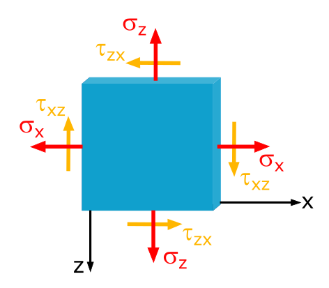
Practice Exercise F-1.2.2-xz
This illustration depicts a square sheet of metal. It lies with two sides in an x, z-coordinate system with the origin at the bottom-left corner of the sheet. The x-axis is positive to the right, and the z-axis is positive downward. Normal and shear stresses are represented for each side of the sheet, with arrows indicating their respective directions.
Determine the Magnitude and Direction of the Principal Stresses in the x-z Coordinate System

In a sheet, the stresses \(\sigma_x = 20\mathrm{~MPa}\), \(\sigma_z = 30\mathrm{~MPa}\) and \(\tau_{xz} = 10\mathrm{~MPa}\) are given.

Determine the magnitude and direction of the principal stresses.

Area Moment of Inertia

Area Moment of Inertia: Calculation of Arbitrarily Shaped Areas Through Integration
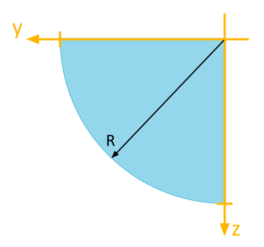
Practice Exercise F-6.1.1
Quarter-circle area for which the moment of inertia (axial, biaxial) is to be calculated. Radius: R, Center of the full circle: y, z, y positive to the left, z positive downward.
Determine the Area Moment of Inertia

For the depicted quarter-circle area, the following area moments of inertia are to be determined with respect to the illustrated \(y\), \(z\)-coordinate system:

  1. Axial Area Moment of Inertia \(I_y\)
  2. Axial Area Moment of Inertia \(I_z\)
  3. Biaxial Area Moment of Inertia \(I_{yz}\)
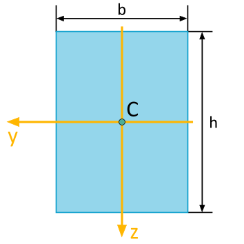
Practice Exercise F-6.1.2
Rectangular area for which the moment of inertia (axial, biaxial) is to be calculated. Width: b, Height: h, Coordinate system y, z with center at the centroid (b/2, h/2), y positive to the left, z positive downward.
Determine the Area Moment of Inertia

For the rectangle area depicted, the following area moments of inertia are to be determined with respect to the illustrated \(y\), \(z\)-coordinate system:

  1. Axial Area Moment of Inertia \(I_y\)
  2. Axial Area Moment of Inertia \(I_z\)
  3. Biaxial Area Moment of Inertia \(I_{yz}\)
Practice Exercise F-6.1.3
Triangular area for which the moment of inertia (axial, biaxial) is to be calculated. Right-angled triangle, right angle in the top-right corner. Base: b, Height: h, Coordinate system y, z with center at the centroid (b/3 from the right side, h/3 from the top), y positive to the left, z positive downward.
Determine the Area Moment of Inertia

For the triangle area depicted, the following area moments of inertia are to be determined with respect to the illustrated \(y\), \(z\)-coordinate system:

  1. Axial Area Moment of Inertia \(I_y\)
  2. Axial Area Moment of Inertia \(I_z\)
  3. Biaxial Area Moment of Inertia \(I_{yz}\)
Practice Exercise F-6.1.4
Circular area for which the moment of inertia (axial, biaxial) is to be calculated. Radius: R, Center: y, z, y positive to the left, z positive downward.
Determine the Area Moment of Inertia

For the circular area depicted, the following area moments of inertia are to be determined with respect to the illustrated \(y\), \(z\)-coordinate system:

  1. Axial Area Moment of Inertia \(I_y\)
  2. Axial Area Moment of Inertia \(I_z\)
  3. Biaxial Area Moment of Inertia \(I_{yz}\)

Area Moment of Inertia: Parallel Displacement of Coordinate Axes - Steiner's Theorem

Practice Exercise F-6.2.1
The illustration depicts a rectangular cross-sectional area with a width of b and a height of h. A yellow y, z-coordinate system is positioned with its origin at the center of the rectangle. A green y-bar, z-bar-coordinate system is situated with its origin at the top-left corner of the rectangle. The y-axes are positive to the left, and the z-axes are positive downward.
Determine Area Moment of Inertia for a Coordinate System Parallel to the Principal Axis System

For the depicted rectangle, the following area moments of inertia are to be determined with respect to the illustrated \(\overline{y}\), \(\overline{z}\)-coordinate system:

  1. Axial Area Moment of Inertia \(I_y\)
  2. Axial Area Moment of Inertia \(I_z\)
  3. Biaxial Area Moment of Inertia \(I_{yz}\)

The area moments of inertia with respect to the principal axes are given as follows:
$$ \begin{align} I_y &= \dfrac{b \cdot h^3}{12} \\[7pt] I_z &= \dfrac{b^3 \cdot h}{12} \\[7pt] I_{yz} &= 0 \end{align} $$
Practice Exercise F-6.2.2
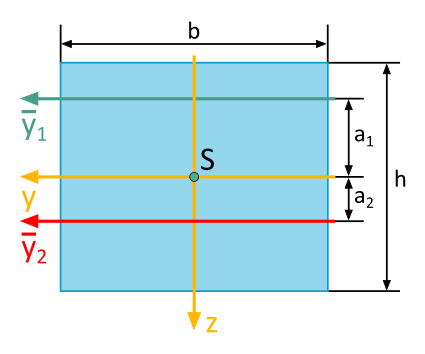
The illustration shows a rectangular cross-sectional area with a width of b and a height of h. A yellow y, z-coordinate system has its origin at the centroid of the area. A green y-bar-subscript-1 axis is located at a-subscript-1 distance above the yellow y-axis. A red y-bar-subscript-2 axis is located at a-subscript-2 distance below the yellow y-axis. The y-axes are positive to the left, and the z-axis is positive downward.
Determine Area Moment of Inertia for a Coordinate System Parallel to the Principal Axis System

The depicted rectangular cross-section has an area of \(A=72~\mathrm{cm}^2\).

The axial area moment of inertia with respect to the \(\overline{y}_1\)-axis (\(a_1 = 5~\mathrm{cm}\)) is known and is \(I_{\overline{y}_1}=2664~\mathrm{cm}^4\).

Calculate the axial area moment of inertia \(I_{\overline{y}_2}\) with respect to the \(\overline{y}_2\)-axis (\(a_2 = 2~\mathrm{cm}\)).