1. Introduction
In the world of engineering mechanics, understanding the behavior of structures and materials is paramount. Whether you're designing a bridge that needs to withstand immense loads or analyzing the stress distribution in a mechanical component, you'll find yourself navigating the intricate landscape of mechanics. At the heart of this journey lies the concept of the Area Moment of Inertia, a fundamental and powerful tool that engineers use to predict and control the response of structures to various forces and loads.
Just as the first moment of area (the centroid) describes the center of mass of a shape, the second moment of area delves deeper into the geometry, characterizing its resistance to bending or flexure. This chapter delves into the essence of this concept, illuminating its applications, mathematical foundations, and practical implications.
We will explore how the Area Moment of Inertia plays a pivotal role in determining deflections, stresses, and stability in structures of all scales. Whether you are a civil engineer designing skyscrapers or a mechanical engineer optimizing a machine component, grasping the intricacies of the Area Moment of Inertia is your ticket to engineering success.
Prepare to embark on a journey through the mathematical intricacies, practical examples, and real-world applications that will empower you to tackle the most challenging engineering problems with confidence and precision. Welcome to the world of the Area Moment of Inertia, where the shaping forces of engineering mechanics are brought to light.
1.1 What is an Area Moment of Inertia?
An area moment of inertia is a geometric property, essentially a shape property. It tells us how well the cross-section of an area can resist changes in a specific direction. This helps us understand how effectively this cross-section can resist bending, shearing, and torsion or twisting. This is especially useful when we want to calculate stresses and deformations in engineering components like beams, supports, and plates.
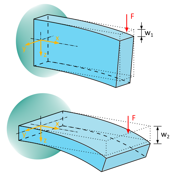
The area moment of inertia depends on the geometry of the cross-section and its orientation relative to the loading. This becomes clear when we look at Figure 6.1.1:

We see a beam with a rectangular cross-section. It is oriented vertically in the upper image and horizontally in the lower image. In both cases, it is loaded by a uniform force F in the \(z\)-direction.
The force F causes the beam to bend. It is easy to imagine that the deformation w1 is much smaller when the beam is oriented vertically compared to the deformation w2 when it is oriented horizontally. This means that the arrangement and orientation of the beam play a crucial role in the magnitude of the deflection under the same load.
This geometric property, which takes into account the arrangement and orientation of a cross-section, is known as the area moment of inertia. It describes the resistance of a beam's cross-section, i.e., an area, against a load and consequently against deformations.
The material of the component does not affect the area moment of inertia. Of course, the material of the component makes a difference in the deformations w1 and w2
The larger the area moment of inertia of a cross-section, the stiffer it is, and the smaller the deformations under a given load. Therefore, the area moment of inertia is a critical parameter in the design and analysis of components in the mechanical, civil, and aerospace industries.