2. First Basic Task: Reduction to a Single Force
Okay, engineer-in-training, pay attention! This is about the first basic task of statics for central force systems: the reduction of a force system to a single force. Sounds complicated? It's not! With a little bit of drawing talent and our clever friend, the forces parallelogram, we can solve the problem in no time.
So, grab your pencil, ruler, and your best buddy, the calculator, and let's go!
Imagine: A rigid body, harassed by three mean forces F1, F2 and F3. They pull, push and drag at it, like wild ants on a piece of candy. But we won't be intimidated! With our brilliant knowledge and a few clever drawings, we'll tame these beasts in no time.
Our goal: We determine the resultant of these three forces. The resultant is a single force that has the same effect as the three individual forces together.
What is a layout diagram? The layout diagram is a scaled drawing that shows the geometric arrangement of all relevant elements of a system. These include:
- Body: The rigid bodies or components to be investigated.
- Supports: The points at which the body is connected to its surroundings.
- Forces: The forces and moments acting on the body.
- Other elements: Dimensions, coordinate systems, etc.
Why is the layout diagram an important tool for solving problems in technical mechanics?
The layout diagram:
- Clarifies the geometric arrangement of the system.
- Enables the determination of angles and lengths.
- Is the basis for the creation of the force diagram
Let's imagine our task had the following layout diagram:
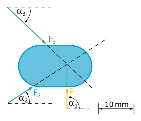
The lines of action of the forces intersect at a point. So we have a central force system.
What is a force diagram? The force diagram is used to graphically represent and analyze the forces acting on an object. In this diagram, the individual forces acting on the structure are drawn as arrows (vectors). The arrow length corresponds to the magnitude of the force and the arrow direction to its direction of action. Accordingly, the scale of a force diagram is force per unit length..
Remember: The force parallelogram is a clever tool for combining two forces into a single force.
- First, we choose an arbitrary starting point S in the force diagram.
- Now we choose two arbitrary forces from the layout diagram (e.g. F1 and F2).
-
We draw the force parallelogram for these two forces. The necessary angles can be read from the layout diagram.
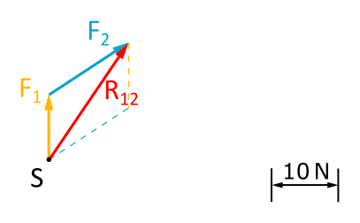
Fig. 3.2.2: Force Parallelogram -
We form the force parallelogram for the resultant of the previous force parallelogram and any other force that we have not yet drawn. In this case, only
F3 remains.
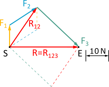
Fig. 3.2.3: Force Parallelogram from all three forces - The resultant of the last force parallelogram is the total resultant.
- Choose a starting point S.
- Draw all force vectors to scale. Start with an arbitrary force vector at the starting point S.
- Gradually draw the other force vectors in any order. Each vector begins at the arrowhead of its predecessor.
- The endpoint E lies at the arrowhead of the last force vector (see Fig. 3.2.3)
- The resultant R is the connecting line from the starting point S to the endpoint E. This means that its direction is opposite to the direction of rotation of the open force polygon (S to E).
- By measuring the length of the resultant, we obtain the magnitude of the resultant, taking into account the scale used.
- We can also measure the direction angle of the resultant.
One question remains: Where is the line of action of the resultant in the layout diagram?
Clearly: Since all forces in the central force system run through one point, the line of action of the resultant must also run through this point:
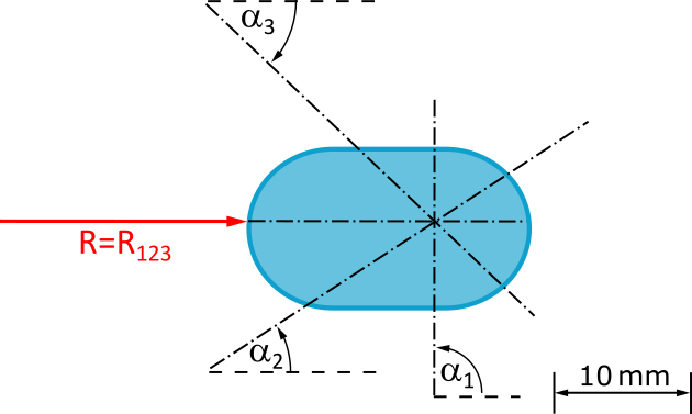
But exactly where on this line of action does the resultant force act? Is our candy being pushed or pulled? The principle of transmissibility of forces provides the answer: We cannot make any statement about this, but it doesn't matter for the effect of the force on the rigid body.
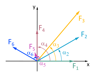
Graphically and analytically determine the magnitude and direction of the resultant force from forces F1 to F6.

Graphically and analytically determine the magnitude and direction of the resultant force from forces F1 to F5.

Graphically and analytically determine the magnitude and direction of the resultant force from forces F1 to F6.