6. Third Basic Task: Decomposition of a Force
Mission: Imagine a force, let's call it R, acting on a rigid body in a plane. Two lines of action, w1 and w2, intersect this force at a point P. Your task? Find two new forces, F1 and F2, along w1 and w2, that together have the same effect as R.
Sounds tricky? With a dash of brainpower and a sprinkle of drawing fun, it's a piece of cake!
Grab your drawing tools and create a scene where you mark the force R and the two directions w1 and w2. This way, you have everything important in sight.

Now, things get magical! Using the Axiom of the Parallelogram of Forces (yes, it's a real thing!), you'll decompose R into the two directions w1 and w2.

You'll notice that there are two paths from S (starting point of R) to E (ending point of R): one via F1 and F2 ...

and one via F2 and F1.

Don't worry, the forces are equal in magnitude and direction, so the solution is unique!
Express this realization as an equation:
Voila! You've found the component representation of R, where F1 and F2 are the component vectors along the directions w1 and w2.
Want to split R in a plane into three directions (w1, w2 and w3)? Then there's more than one solution!

In the force plan, you'll find different ways to divide R.

For example, if you change the magnitude of F1, the magnitudes and possibly the directions of the other forces will also change.

So, the solution is not unique. There are infinitely many ways to split the forces. Depending on the magnitude and direction you choose for one force, you'll get different solutions.
- Decomposing a force in a plane into two directions yields a unique solution.
- In a plane, with more than two directions, there are infinitely many solutions.
In space (3D):
- Decomposing a force in space into three directions yields a unique solution if the directions are not in the same plane and not parallel.
- In space, with more than three directions, there are infinitely many solutions.
A force F = 25 N is to be decomposed into two components F1 and F2 which are perpendicular to each other. The lines of action of F and F1 are to form an angle \(\alpha = 35°\).
Determine the magnitudes of F1 and F2 graphically and analytically.

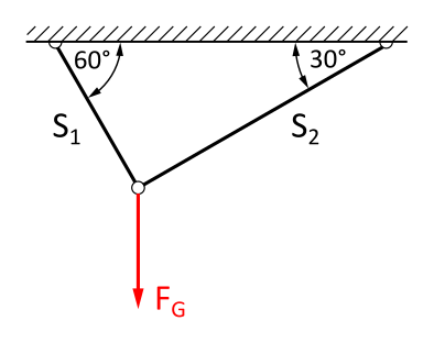
A mass with the weight force FG is hanging on two ropes.
What are the components of the force FG = 10 kN in the direction of ropes 1 and 2?