2.3.3 Reading Stresses from the Mohr's Circle of Stress
In the previous section, we worked on how to draw Mohr's circle when we know the normal stress \(\sigma_x\). Now, we will learn how to read stresses at any arbitrary angle from the Mohr's stress circle for the uniaxial stress state.
Before we discuss how to read values on the Mohr's stress circle, here are two notes:
Note 1: The Included Angle is Represented as Twice the Angle in the Stress Circle!
During the derivation of the circle equation for the stress circle, we used the original formulas (1.4) and (1.5xy) or (1.5xz) that contained twice the included angle \(2\varphi\).
Accordingly, the included angle in Mohr's circle is read or plotted with twice the angle.
Note 2: Counting Direction of the Angle \(2\varphi\) on Mohr's Circle
While the included angle \(\varphi\) is counted as positive in the possible \(x\), \(y\), or \(x\), \(z\) coordinate systems on the component counterclockwise (see Right-Hand Rule in Cartesian coordinate systems + Right-Hand Thumb Rule for determining the positive direction of rotation), the counting direction of the angle \(2\varphi\) in Mohr's circle depends on both the coordinate system used (see Fig. 1.2.6, Fig. 1.2.7) and the choice of the \(\tau\)-axis direction (see Fig. 1.2.15).
You can determine the positive direction of the angle \(2 \varphi\) in Mohr's Circle for a desired combination of the coordinate system used and the \(\tau\)-axis direction by using the formula 1.5xy or 1.5xz, depending on the used coordinate system. Insert any positive or negative normal stress \(\sigma_x\) and a positive cutting angle \(\varphi = 45°\)."
Since \(\sin(2\cdot45°) = \sin(90°) = 1\), the shear stress for this angle can be easily determined: \(\tau = -\frac{\sigma_x}{2}\) in the \(x,y\)-coordinate system and \(\tau = \frac{\sigma_x}{2}\) in the \(x,z\)-coordinate system.
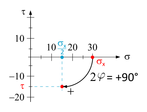
Now, when sketching the \(\tau,\sigma\)-coordinate system with the desired \(\tau\)-axis direction, either positively upward or downward, and plotting the used normal stress \((\sigma_x|0)\) and the calculated shear stress \((\frac{\sigma_x}{2}|\tau)\), the positive counting direction is the shortest angle arc from \((\sigma_x|0)\) to \((\frac{\sigma_x}{2}|\tau)\), as this angle must be \(2\cdot\varphi = +90°\) in the equation 1.5xy or 1.5xz.
Example (refer to Table 1.2.1, No. 1):
- \(x, y\)-coordinate system
- \(\tau\)-axis direction positively upward
Chosen: \(\sigma_x = 30~ \mathrm{N/mm^2}\)
Calculated: \(\tau = - \frac{\sigma_x}{2}\cdot 1 = -15~ \mathrm{N/mm^2}\)
Sketch:

Therefore, the positive counting direction of the angle \(2\varphi\) is clockwise in a Mohr's Circle with an upward positive \(\tau\)-axis. This is applied when using the \(x, y\)-coordinate system (with \(y\)-axis positively upward) for the cutting angle on the component.
This positive counting direction, of course, applies to all Mohr's Stress Circles that combine this \(\tau\)-axis direction with the \(x, y\)-coordinate system (with \(y\)-axis positively upward) on the component.
The following table illustrates the direction of rotation of the angle \(2\varphi\) in Mohr's Circle when positively counted in any combination of the coordinate system used and the \(\tau\)-axis direction:
Positive Direction of Angle \(2\varphi\) in the Mohr's Stress Circle
| No. | Coordinate System | \(\tau\)-Axis Orientation | Positive Counting Direction | ||
| 1 |  |
\(+\) |  |
\(\Rightarrow\) |  |
| 2 |  |
\(+\) |  |
\(\Rightarrow\) |  |
| 3 |  |
\(+\) |  |
\(\Rightarrow\) |  |
| 4 |  |
\(+\) |  |
\(\Rightarrow\) |  |
What can we Generally Read from Mohr's Circle?
The maximum and minimum normal stresses that can occur in the given stress state are the two intersection points of the stress circle with the \(\sigma\)-axis.
For tensile stress, the maximum normal stress is \(\sigma_x\), and the minimum normal stress is \(0\), while for compressive stress, the maximum normal stress is \(0\), and the minimum normal stress is \(\sigma_x\).
The starting point for measuring the angle \(2\varphi\) is always at the applied normal stress \(\sigma_x\). This is necessary because the cutting angle on the component must be \(\varphi = 0°\).
Therefore, for both tensile and compressive loading, the normal stress \(0\) is obtained when we read the angle \(2\varphi = 180°\) on the stress circle. This corresponds to an angle of \(90°\) at the component due to the double angle in the stress circle.
The last general information from the stress circle is that the magnitude of the maximum shear stress \(|\tau_{max}|\) is equal to the circle's radius \(|\frac{\sigma_x}{2}|\).
Reading Example for a Section Angle \(\varphi = 67.5°\)
We are looking for the normal and shear stresses that occur at a section angle of \(\varphi = 67.5°\) for the most commonly used \(x, y\)-coordinate system, using two Mohr's stress Circles (one with a positive upward \(\tau\)-axis direction and one with a positive downward \(\tau\)-axis direction):
- For tensile stress \(\sigma_x=200~\frac{\mathrm{N}}{\mathrm{mm^2}}\), the normal and shear stresses occurring at a section angle of \(\varphi = 67.5°\)
- For compressive stress \(\sigma_x=-200~\frac{\mathrm{N}}{\mathrm{mm^2}}\), the normal and shear stresses occurring at a section angle of \(\varphi = 67.5°\)
First, we draw the stress circles according to the four steps we know:
- Draw the four \(\sigma, \tau\)-coordinate systems: The \(\sigma\)-axis always runs horizontally to the right, and the \(\tau\)-axis runs vertically upward positively and vertically downward positively, each twice.
- Plot the normal stress \(\sigma_x\) on the \(\sigma\)-axis, considering its sign. Choose a suitable scale that must be the same for both the \(\sigma\) and \(\tau\) axes, for example, \(1 ~\mathrm{cm}\) per \(50 ~\frac{\mathrm{N}}{\mathrm{mm^2}}\).
- The circle's center is located halfway between \(\sigma_x\) and the \(\tau\)-axis, at \(\frac{\sigma_x}{2}\).
- With this information, you can draw the stress circle using a compass.
Now we can read the desired normal and shear stresses. Pay attention to the counting direction of the angle \(2\varphi\) for the stress circles used (see Table 1.2.1) and the fact that the starting point of the angle \(2\varphi\) is always at the applied normal stress \(\sigma_x\), regardless of whether it's tensile or compressive stress. This is because the section angle \(\varphi = 0°\) here.

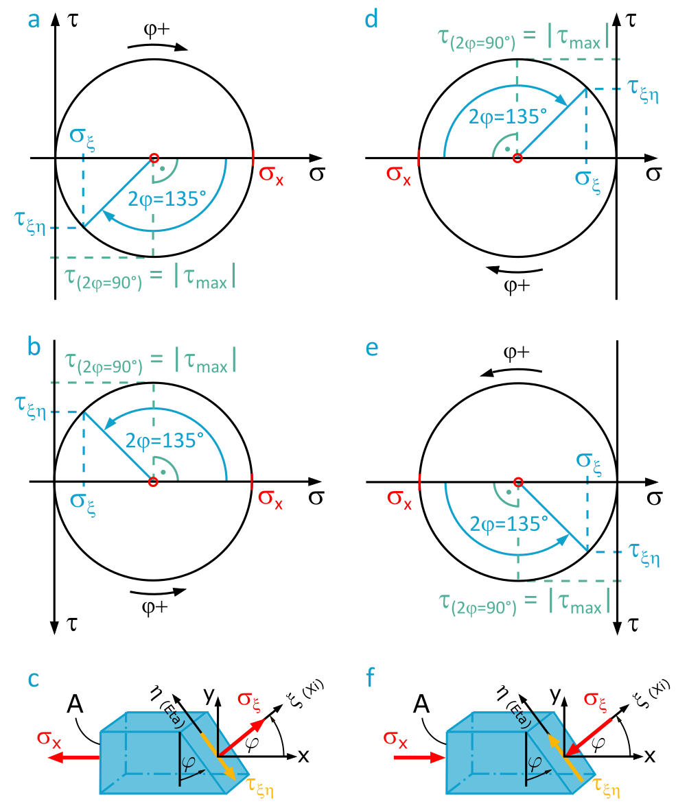
Figure 1.2.17 shows the reading results for a section angle \(\varphi = 67.5°\), i.e., \(2\varphi = 135°\):
- For tensile stress \(\sigma_x = 200~\frac{\mathrm{N}}{\mathrm{mm^2}}\) (a, b,
c) :
\(\sigma_{\xi} = +29 ~\frac{\mathrm{N}}{\mathrm{mm^2}}\), \(\tau_{\eta\xi} =-70 ~\frac{\mathrm{N}}{\mathrm{mm^2}}\) - For compressive stress \(\sigma_x = -200~\frac{\mathrm{N}}{\mathrm{mm^2}}\) (d, e,
f) :
\(\sigma_{\xi} = -29 ~\frac{\mathrm{N}}{\mathrm{mm^2}}\), \(\tau_{\eta\xi} = +70 ~\frac{\mathrm{N}}{\mathrm{mm^2}}\)
Taking into account the starting point and counting direction of the angle \(2\varphi\), it becomes clear: The magnitude of the maximum shear stress \(|\tau_{max}| = |\frac{\sigma_x}{2}|\) occurs at a 45° section angle (\(2\varphi=90°\)) to the applied load.